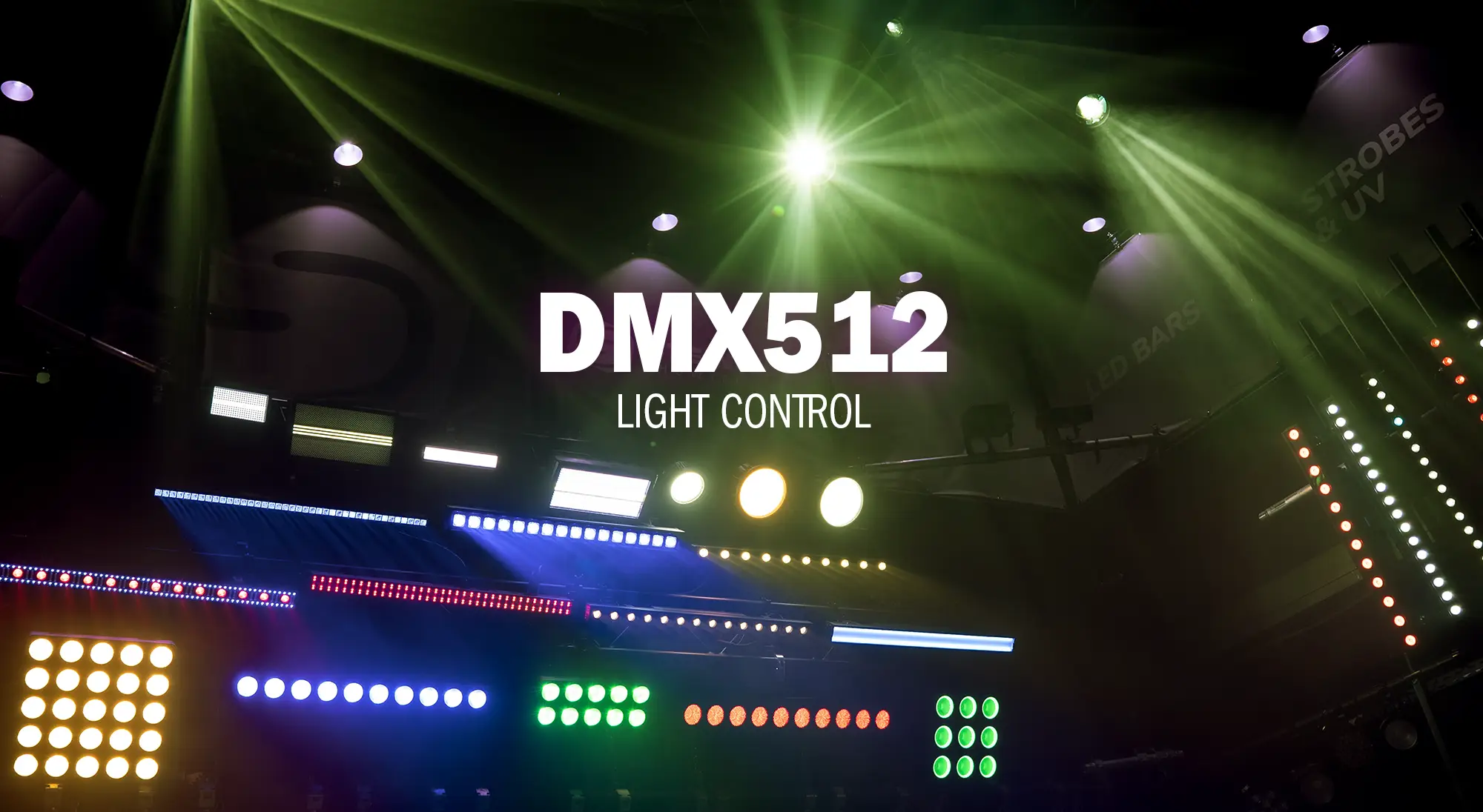
One LED fixture should shine blue, a second red and a third slowly get brighter. For these actions to work as intended, the devices need the appropriate control data. In event technology, this task is often handled by the “Digital Multiplex” control protocol, or DMX512 for short. The underlying principle is straightforward: A controller sends values, and each fixture reads the channels assigned to it.
Contents
1. How Does DMX Control Work?
The transmitter might be a lighting console or a computer with lighting software and a DMX interface. The controller continuously transmits the channel values in sequence. All devices on the same DMX line receive the data stream. Each device uses its configured start address to determine which section of the stream to read.
Basic DMX control operates in one direction: from the controller to the receivers. Automatic feedback from the fixture is not part of this basic principle. For remote configuration and feedback, DMX can be supplemented with RDM, provided the components involved support it.
2. What Are DMX Channels and Start Addresses?
A DMX channel carries a single control value. On an LED fixture, for example, a channel might be dedicated to the intensity of the red LEDs, the master dimmer or a strobe effect. One channel, therefore, does not represent an entire fixture. Devices with multiple functions require more channels.
The start address determines the first DMX channel a device responds to. A fixture with seven channels and a start address of 1 uses addresses 1 through 7. With a start address of 8, its range shifts to 8 through 14. For proper control, these channel ranges must not overlap.
The number of channels a fixture requires depends on the selected DMX mode. Many devices offer several modes with different sets of functions. The channel assignments in the user manual are therefore crucial: Channel 1 may control the dimmer on one model and a color on another. The meaning of individual value ranges is also specific to each device.
3. How Is a DMX Universe Structured?
A DMX universe is an address space containing 512 channels, numbered from 1 to 512. This number refers to the available control channels, not a fixed number of fixtures that can be connected, since lighting and effects devices use different numbers of channels depending on the model. The devices’ channel ranges are assigned within this address space.
For example, with no gaps in the channel assignments, 73 independently controllable fixtures with seven channels each fit into one universe: 73 × 7 equals 511. Channel 512 remains unused. However, this calculation only accounts for channel usage. The electrical load capacity of a line and the need to distribute devices across multiple branches must also be considered.
If 512 channels are not enough, another universe is added. Addressing starts at 1 again in that universe. Together, the universe and start address make the assignment unambiguous, for example, “Universe 2, Address 15.” DMX addressing for a fixture can, therefore, be compared to a person’s home address, which also distinguishes between a city, street and house number.
4. DMX Addressing in Practice: Three Fixtures with Seven Channels Each
The following example uses three identical, hypothetical LED fixtures. All operate in a seven-channel mode. The assumed channel assignments are for illustrative purposes and must be checked against the user manual when working with an actual device.
| Function in This Example | Fixture 1 | Fixture 2 | Fixture 3 |
|---|---|---|---|
| Master dimmer | Channel 1 | Channel 8 | Channel 15 |
| Red | Channel 2 | Channel 9 | Channel 16 |
| Green | Channel 3 | Channel 10 | Channel 17 |
| Blue | Channel 4 | Channel 11 | Channel 18 |
| White | Channel 5 | Channel 12 | Channel 19 |
| Strobe | Channel 6 | Channel 13 | Channel 20 |
| Program selection | Channel 7 | Channel 14 | Channel 21 |
| Start address | 1 | 8 | 15 |
For DMX addressing with no gaps, the following rule applies:
Next start address = current start address + number of channels
After the first device, this gives 1 + 7 = 8, and after the second, 8 + 7 = 15. The third device ends at channel 21. A fourth seven-channel device could start at address 22. Leaving gaps between devices is also possible, but not necessary.
Setup involves three steps:
- 1. Select seven-channel mode on all fixtures.
- 2. Set the start addresses to 001, 008, and 015.
- 3. In the controller, set up the devices with the appropriate channel assignments, the same mode and their respective addresses in the correct universe. This assignment is called the “patch.”
To make the second fixture shine red in this example, the relevant controls are the master dimmer on channel 8 and red on channel 9. Green, blue and white remain at zero; strobe and program selection must be set to the values specified in the user manual for static light. Turning up a color channel alone will not produce light if the master dimmer is at zero.
5. How Are DMX Devices Connected?
Devices are typically connected in a daisy chain: The controller’s DMX output connects to the first device’s DMX input. That device’s DMX output connects to the input of the next device. The order of the devices in the cable run does not determine their addresses.
For mobile applications, the standard specifies five-pin XLR connectors; in practice, three-pin connectors are also common. The connections are made using suitable DMX cables. A microphone cable may have matching connectors, but its different electrical characteristics mean it is not a reliable substitute. A DMX splitter can be used to create branches.
At the end of each line, a 120-ohm resistor connected between the data lines can provide termination. In practice, however, these termination resistors sometimes cause problems themselves. If the fixtures on a line start flickering, removing the termination resistor is often a useful first troubleshooting step.
6. Common Addressing and Cabling Mistakes
Overlapping addresses: If the second seven-channel fixture in our example starts at address 7, both devices share that channel. In this example, it must start at address 8 or higher.
Mismatched channel modes: A seven-channel mode on the device and a different fixture profile in the controller will result in incorrect function assignments. The mode and patch must match.
Unintentionally duplicated start addresses: Identical devices with the same channel assignments will then respond together to the same values. This can be useful for groups, but it prevents independent control.
Unsuitable cables or passive Y-splitters: Suitable DMX cables and active splitters help ensure stable data transmission.
No light output despite a signal: In addition to the address and mode, check the master dimmer, blackout and selected operating mode. If the cause of a problem is unclear, test one fixture on its own: Connect it directly to the controller using a short, tested DMX cable.
7. Conclusion: What Is DMX512?
DMX stands for “Digital Multiplex.” DMX512 is a digital control protocol for lighting equipment and other devices used in event technology. It was standardized by USITT (United States Institute for Theatre Technology). A DMX universe contains up to 512 control channels, and each channel transmits a value between 0 and 255. The function affected by that value is determined by the device’s DMX channel assignments, which are often listed under “DMX protocol” in the fixture’s user manual.